
PIR sensors, combined with manual override functionality, offer enhanced control for lighting and security systems. These systems provide automated operation alongside user intervention, ensuring convenience and adaptability.
What is a PIR Sensor?
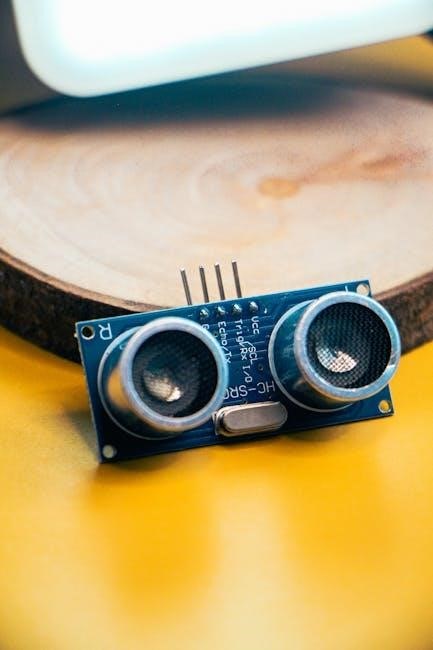
PIR (Passive Infrared) sensors are electronic devices that detect changes in infrared radiation. Essentially, they sense motion by identifying differences in heat signatures. Unlike active sensors that emit energy, PIR sensors are passive – they only detect existing infrared emissions from objects in their field of view.
These sensors are widely used in security systems, automatic lighting, and occupancy detection. They work by detecting changes in infrared levels caused by moving heat sources, like people or animals. A Fresnel lens is often used to focus the infrared light onto the sensor, increasing its sensitivity and range. When motion is detected, the sensor triggers an electrical signal, activating a connected device, such as a light or alarm. They are a cost-effective and reliable solution for motion detection.
The Need for Manual Override
While PIR sensors excel at automated control, situations arise where manual operation is crucial. Automatic systems can be inconvenient when continuous illumination is needed, regardless of motion – for tasks or extended periods. A manual override feature addresses this limitation, allowing users to bypass the sensor’s automatic function and directly control the connected device, like a light.
This functionality is particularly valuable for security applications, enabling users to switch lights on even without detected motion. It also provides a convenient solution for areas requiring constant illumination, eliminating the need for repeated triggering. The ability to switch between automatic and manual modes enhances the system’s flexibility and user experience, making it more adaptable to diverse needs.

Components and Circuitry
Essential components include a PIR sensor, relay, manual override switch, LED indicator, and appropriate resistors. These elements work together to create a functional and controllable system.
PIR Sensor Basics
Passive Infrared (PIR) sensors detect changes in infrared radiation, essentially sensing motion by identifying differences in heat signatures. They don’t emit energy; instead, they passively receive it. Inside, a Fresnel lens focuses infrared radiation onto a pyroelectric sensor. When a warm body moves across the sensor’s field of view, the varying infrared levels trigger a detection signal.

These sensors are commonly used in security systems and automated lighting. The sensitivity, adjustable via a potentiometer (SENS), determines the range of detection. Understanding these core principles is crucial for integrating a PIR sensor with a manual override, allowing for both automatic and user-controlled operation. Proper placement and adjustment are key to reliable performance.
Relay Integration with PIR Sensors
Relays act as electrically operated switches, enabling a low-voltage PIR sensor to control high-voltage circuits, like 220V AC lighting. The PIR sensor’s output signal activates the relay’s coil, closing or opening the circuit. This isolation is vital for safety, preventing direct connection between the low-voltage sensor and the mains power.
When integrating, the PIR sensor connects to the relay’s control input. The relay’s contacts then switch the power to the load (e.g., a light). Careful consideration of the relay’s coil voltage and contact current rating is essential. Proper wiring, connecting the permanent live to the common (COM) terminal and the switched live to the normally open (NO) terminal, ensures correct operation with the PIR’s signal.
Manual Override Switch Implementation
Manual override switches provide users with direct control, bypassing the PIR sensor’s automatic operation. Typically, a simple push-button switch is employed, altering the circuit to force the relay into an ‘on’ state, regardless of motion detection. This is useful for maintaining constant illumination when needed, overriding the sensor’s timed functionality.
Wiring involves connecting the switch in parallel with the PIR sensor’s output. Pressing the switch effectively simulates continuous motion detection, keeping the relay energized. A second press often reverts the system to standard PIR mode. The switch should be wired to a low-voltage DC source, ensuring compatibility with the PIR sensor’s logic level. This setup allows for convenient, on-demand control.
LED Indicator for Override Status
An LED indicator is crucial for visually confirming the manual override state. Typically, a blue LED is used to signal constant activation, clearly differentiating it from motion-triggered operation. This provides immediate feedback to the user, indicating whether the system is responding to movement or operating in override mode.
The LED is connected in series with a current-limiting resistor to the override switch output. When the switch is activated, it energizes the LED, providing a clear visual cue. Selecting the appropriate resistor value is vital to ensure sufficient brightness without damaging the LED. This simple addition significantly enhances usability, allowing for quick status assessment without needing to observe the connected load.

Resistor Selection for LED and PIR Circuit
Resistor selection is critical for both the LED indicator and the PIR sensor circuit’s proper function. For the LED, a resistor limits current to prevent damage, calculated using the LED’s forward voltage, desired current, and the supply voltage. Typically, values between 220Ω and 1kΩ are used, depending on the LED’s specifications.
Within the PIR circuit itself, resistors are often integrated into the sensor module for bias and timing. However, external pull-up or pull-down resistors might be necessary for the output signal, ensuring a defined logic level when no motion is detected. Careful consideration of resistor values impacts sensitivity and stability, influencing the PIR sensor’s overall performance and reliability.

Wiring and Installation
Proper wiring connects the PIR sensor, relay, manual override switch, and power supply (220V AC). Safety is paramount; always disconnect power before installation.
Connecting the PIR Sensor to the Relay
Establishing a connection between the PIR sensor and the relay is crucial for automated control. Typically, the PIR sensor’s output signal, which activates upon motion detection, is connected to the relay’s control input. This signal energizes the relay coil, closing the circuit and switching the connected load – often lighting – on.
Ensure correct polarity if the PIR sensor specifies it. The relay acts as an intermediary, allowing a low-voltage signal from the PIR sensor to control a high-voltage circuit. Careful consideration of the relay’s coil voltage and current requirements is essential for reliable operation. Proper wiring ensures that motion detected by the PIR sensor reliably triggers the relay, activating the desired output.
Wiring the Manual Override Switch
The manual override switch introduces user control, bypassing the PIR sensor’s automatic function. Wiring typically involves a parallel connection to the relay’s coil circuit. One terminal of the switch connects to the power supply’s positive line, while the other connects directly to the relay coil.
This configuration allows the switch to directly energize the relay, regardless of the PIR sensor’s state. When the switch is activated, it forces the relay to close, maintaining the connected load’s power. Crucially, the switch should be rated for the voltage and current of the circuit. This setup enables users to maintain constant illumination, overriding the motion-activated functionality when needed.
Power Supply Considerations (220V AC)
When utilizing a 220V AC power supply, safety is paramount. The power supply must be adequately rated to handle the combined current draw of the PIR sensor, relay coil, LED indicator, and the connected load (e.g., lights). A fused power supply is highly recommended to protect against overcurrents and short circuits.
Ensure proper grounding of the power supply enclosure to prevent electrical shock. Always disconnect power before making any wiring connections. Use appropriately insulated wires rated for 220V AC. Remember to connect the permanent live to the common (COM) terminal of the override switch, and the switched live from the PIR to another COM terminal.

Safe Wiring Practices ⎼ Live and Neutral Connections
Crucially, always disconnect the 220V AC power supply before commencing any wiring. Identify the live and neutral wires correctly – incorrect connections can be extremely dangerous. The live wire carries the voltage, while the neutral provides the return path.
Connect a permanent live to the COM terminal of the manual override switch. The switched live output from the PIR sensor should connect to the COM terminal of another switch, with L1 terminals linked to the light fitting’s live supply. Ensure all connections are secure and insulated to prevent shorts. Double-check wiring before restoring power, and consider using a qualified electrician if unsure;

Programming and Code (Arduino Example)
Arduino code manages the PIR sensor and manual override. Defining pins for the override switch, LED status, and relay control enables automated and user-controlled operation.
Setting up the PIR Override Pin
Establishing the PIR override pin within the Arduino sketch is crucial for implementing the manual control feature. This pin, digitally defined in the code (e.g., int PIR_override = 3;), acts as the input for the manual override switch.
The code will continuously monitor the state of this pin. When the switch connected to this pin is pressed, it signals the microcontroller to transition between automatic PIR detection mode and a constant-on, overridden state.
Proper pin assignment is vital; avoid using pins reserved for other functionalities. The INPUT_PULLUP mode is often employed to simplify wiring by utilizing the Arduino’s internal pull-up resistor, eliminating the need for an external one. This ensures a defined state when the switch is not pressed, preventing erratic behavior.
Defining the Override Status and Relay Pins
Within the Arduino code, clearly defining pins is essential for controlling the relay and indicating override status. The relaypin (e.g., int relaypin = 13;) dictates which digital pin activates the relay, switching the connected load (lights) on or off. Simultaneously, the overridestatus pin (e.g., int overridestatus = 12;) manages the LED, visually confirming manual override activation.
These pin assignments must align with the physical wiring connections. Using descriptive variable names enhances code readability and maintainability. Initializing these pins as OUTPUT allows the Arduino to send signals to control the relay and LED.
Correct pin definitions are paramount for the system’s functionality, ensuring the relay and LED respond accurately to both PIR sensor input and manual override commands.
Implementing the Manual Override Logic
The core of the manual override lies in toggling the system between PIR-triggered and constant-on modes. The Arduino code monitors the PIR_override switch. A single press activates the override, setting the overridestatus variable to ‘ON’ and energizing the relay, bypassing the PIR sensor. The LED illuminates, visually confirming the override.
A subsequent press reverts to PIR mode, deactivating the override, and allowing motion detection to control the relay. This toggle is achieved using an if-else statement, checking the switch’s state and updating the relay and LED accordingly.
Debouncing the switch is crucial to prevent multiple triggers from a single press, ensuring reliable operation. This logic provides users with convenient, on-demand control.
Advanced Features and Considerations
PIR sensors offer adjustable sensitivity (SENS), on-time (TIME), and twilight sensor functionality for customized operation, alongside IP65 environmental protection.

Adjustable Sensitivity (SENS)
Adjustable sensitivity, often labeled as SENS on the PIR sensor module, is a crucial feature for optimizing performance in various environments. This control allows users to fine-tune the sensor’s detection range, minimizing false triggers caused by small animals, moving branches, or changes in temperature.
Lowering the sensitivity reduces the detection range, making the sensor less prone to nuisance alarms. Conversely, increasing the sensitivity expands the detection area, ideal for larger spaces or when detecting subtle movements is necessary. Proper adjustment ensures reliable motion detection without unwanted activations, enhancing the overall usability and effectiveness of the PIR sensor system, especially when combined with manual override capabilities.
Adjustable On-Time (TIME)
The adjustable on-time, typically marked as TIME on the PIR sensor, dictates how long the connected load (e.g., a light) remains active after motion is detected. This setting is vital for customizing the system to specific needs and preferences. Shorter durations are suitable for quick, momentary illumination, while longer durations provide extended lighting for tasks or security purposes.
A typical range for this adjustment is from a few seconds to several minutes. When integrated with a manual override, the TIME setting influences how long the light stays on after the override is deactivated and the sensor reverts to automatic mode. Careful calibration of the TIME setting optimizes energy efficiency and user convenience, ensuring the system responds appropriately to detected motion.
Twilight Sensor Functionality
Many PIR sensors incorporate a built-in twilight sensor, also known as a light level sensor, enhancing their efficiency and usability. This feature allows the sensor to operate only during periods of low ambient light, preventing unnecessary activation during daylight hours. The sensitivity of this sensor is often adjustable, enabling users to define the precise light level at which the PIR sensor becomes active.
When combined with a manual override, the twilight sensor continues to function, influencing when the sensor can activate in automatic mode. Even in override, the sensor won’t trigger if it’s too bright. This functionality is particularly useful for outdoor lighting, ensuring illumination only when needed, conserving energy and extending the lifespan of the connected load.
IP Ratings and Environmental Protection (IP65)
IP ratings define the level of protection a device offers against solid objects and liquids. An IP65 rating, commonly found in outdoor PIR sensors with manual override, signifies dust-tight protection and resistance to water jets from any direction. This makes them suitable for exposed locations, like gardens or building exteriors, where weather conditions can be harsh.
Choosing a sensor with an appropriate IP rating is crucial for longevity and reliable performance. Even with a manual override feature, the internal components must be shielded from the elements. IP65 rated sensors ensure continued functionality, preventing corrosion and electrical faults. This robust protection guarantees consistent operation, regardless of environmental challenges, alongside the convenience of manual control.

Troubleshooting Common Issues
Common problems include a constantly active LED/relay or a PIR sensor failing to detect motion; checking wiring and sensor settings is essential for resolution.
LED and Relay Constantly Active
If the LED indicator and relay remain constantly activated, despite the absence of motion, several issues could be present. First, carefully examine the Arduino code for logical errors within the manual override section. A persistent high signal to the relay pin, due to a coding flaw, will cause this behavior.
Secondly, inspect the wiring connections, particularly those related to the manual override switch. A short circuit or a permanently closed switch could be bypassing the PIR sensor’s control. Ensure the switch is functioning correctly and not stuck in the ‘on’ position.
Finally, verify the PIR sensor itself isn’t malfunctioning and sending a continuous high signal. Test the sensor’s output independently to confirm its behavior. A faulty sensor might require replacement.
PIR Sensor Not Detecting Motion
If the PIR sensor fails to detect motion, begin by checking the sensitivity (SENS) adjustment. A low sensitivity setting might limit the detection range. Increase it gradually and retest. Also, verify the time (TIME) setting isn’t too short, causing the sensor to quickly return to standby. Ensure there are no obstructions blocking the sensor’s field of view.
Confirm the power supply is stable and providing sufficient voltage to the PIR sensor. Low voltage can impair its performance. In manual override mode, remember the sensor’s motion detection is bypassed; ensure you’ve switched back to automatic mode for testing.
Finally, consider environmental factors; extreme temperatures or direct sunlight can affect sensor accuracy. A faulty sensor may require replacement.